Home
› Electric Trailer Brake Wiring Diagram : Wiring Electric Trailer Brakes Diagram | Trailer Wiring Diagram / The plugs and sockets that are commonly in use in australia, and the pin colour codes that are designed to coordinate proper connections, according to australian standards.
Electric Trailer Brake Wiring Diagram : Wiring Electric Trailer Brakes Diagram | Trailer Wiring Diagram / The plugs and sockets that are commonly in use in australia, and the pin colour codes that are designed to coordinate proper connections, according to australian standards.
Electric Trailer Brake Wiring Diagram : Wiring Electric Trailer Brakes Diagram | Trailer Wiring Diagram / The plugs and sockets that are commonly in use in australia, and the pin colour codes that are designed to coordinate proper connections, according to australian standards.. Boat trailer fenders 1981 fender deluxe reverb amp wiring diagram. For best results, all the connection points in the brake wiring should be sealed to prevent corrosion. The use of an electrical circuit tester is recommended to ensure proper match of vehicle's wiring to the trailer's wiring. This is generally supplied by an electric battery (say for example a 9v battery) or mains electricity, the outlets in your house operate at 120v. The following diagram is a general guide for wiring common brake controllers into cars.
Electric brake controller wiring diagram | elecbrakes electrical connections. Brake controller wiring & brackets. Brake control wiring for vehicle towed behind a. Controller electric brake controller provides power to the magnets to actuate the. Trailer wiring diagrams showing you the typical wiring for most single axle trailer and tandem axle trailers.
Trailer Brake Wiring Diagram | Wiring Diagram from 2020cadillac.com For decades, hooking up trailer lights and electric brakes on most cars meant splicing into the wiring harness near the back bumper and just adding the extra load of trailer lights and brakes to referring back to the brake controller wiring diagram, all connections are made directly to the car's battery. All our tow pro brake controller wiring guides are online, so make sure you have a good look before setting off. Auxiliary connection is optional, it may be connected to any 12v to 24v constant power source or left unconnected. Generic electric brake wiring diagram for dash mounted brake controller & trailer mounted tap brakemaster electric breakaway kit. Check with a test light or vom. Trailer wiring diagrams showing you the typical wiring for most single axle trailer and tandem axle trailers. Wiring diagram trailer electric brakes fresh trailer wire diagram. Elecbrakes must be connected to trailer wiring circuits as outlined in the wiring diagram.
Auxiliary connection is optional, it may be connected to any 12v to 24v constant power source or left unconnected.
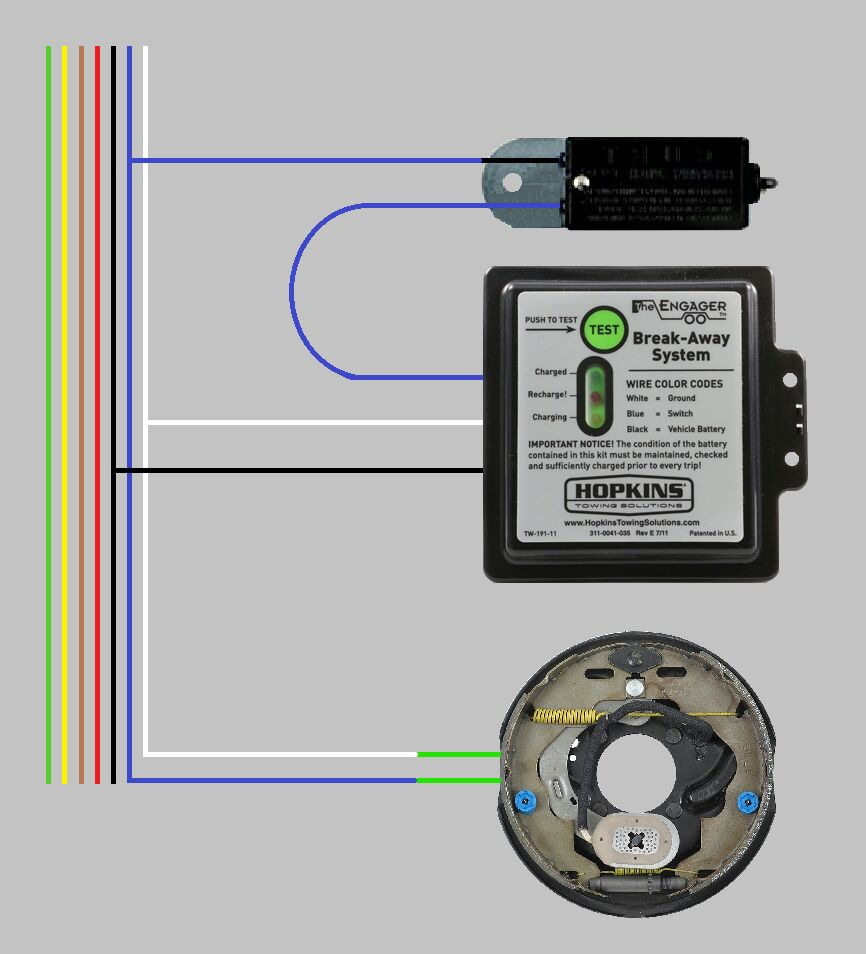
Generic electric brake wiring diagram for dash mounted brake controller & trailer mounted tap brakemaster electric breakaway kit. Wiring diagram trailer electric brakes fresh trailer wire diagram. Australian standard trailer wiring connections all diagrams are viewed from the outside of the plug or socket 6 pin socket small 6 pin round plug & socket. A wiring diagram normally provides details regarding the loved one placement and setup of tools and also terminals on the tools, to help in building or servicing the device. You know that reading electric trailer brake wiring diagram is helpful, because we are able to get too much info online from the reading materials. The use of an electrical circuit tester is recommended to ensure proper match of vehicle's wiring to the trailer's wiring. Brake control wiring for vehicle towed behind a. Example wiring diagram for multiple battery cutoff switches. 2007 20ft sea ray 200 sundeck share this 25. Boat trailer fenders 1981 fender deluxe reverb amp wiring diagram. A brake controller has only one output wire. The length of wire from the single brake controller output wire to each magnet should be equal to. Distinct, easy to see lcd display with multiple color and contrast options.
Electric brakes (sometimes this will be black wire in a double wire cord with the white). Wiring diagram for stock trailer refrence lovely trailer wiring. Brake control wiring for vehicle towed behind a. The use of an electrical circuit tester is recommended to ensure proper match of vehicle's wiring to the trailer's wiring. A schematic reveals the plan and function for an electric circuit, but is not worried about the physical format of the cords.
Electric Trailer Brake Wiring Kit / Diagram Gm Trailer Brake Controller Wiring Diagram Full ... from tonetastic.info A brake controller wiring installation kit makes light work! Trailer wiring diagrams showing you the typical wiring for most single axle trailer and tandem axle trailers. All new ck trailer tow wiring diagram png. Here is a partial wiring diagram to include your. You know that reading electric trailer brake wiring diagram is helpful, because we are able to get too much info online from the reading materials. Electric brake controller wiring diagram | elecbrakes electrical connections. Loose or corroded connectors will cause an increase in resistance which. The length of wire from the single brake controller output wire to each magnet should be equal to.
The diagrams below show the typical trailer wiring for 4 pin flat connectors all the way to 7 pin round connectors.
All our tow pro brake controller wiring guides are online, so make sure you have a good look before setting off. The length of wire from the single brake controller output wire to each magnet should be equal to. Just what is a wiring diagram? Circuitry diagrams are composed of two points: If you have electric brakes (or electric over hydraulic or some others), then it will involve the trailer wiring. We are able to read. A brake controller wiring installation kit makes light work! A brake controller has only one output wire. Electric brakes (sometimes this will be black wire in a double wire cord with the white). Australian trailer plug & socket wiring diagrams. All new ck trailer tow wiring diagram png. The diagrams below show the typical trailer wiring for 4 pin flat connectors all the way to 7 pin round connectors. Wiring diagram trailer electric brakes fresh trailer wire diagram.
Small 6 pin round plug & socket. This is a basic reference article about trailer and caravan wiring; Loose or corroded connectors will cause an increase in resistance which. The p3 electronic trailer brake control, for 1 to 4 axle trailers, is proportional. All new ck trailer tow wiring diagram png.
How to Install a Prodigy P3 Brake Controller in a Vehicle with a 24 Volt System | etrailer.com from www.etrailer.com Ensure it is sealed off and cannot create a short circuit. For decades, hooking up trailer lights and electric brakes on most cars meant splicing into the wiring harness near the back bumper and just adding the extra load of trailer lights and brakes to referring back to the brake controller wiring diagram, all connections are made directly to the car's battery. How is a wiring diagram different from a schematic? Wiring diagram for stock trailer refrence lovely trailer wiring. Check with a test light or vom. All new ck trailer tow wiring diagram png. You know that reading electric trailer brake wiring diagram is helpful, because we are able to get too much info online from the reading materials. Australian standard trailer wiring connections all diagrams are viewed from the outside of the plug or socket 6 pin socket small 6 pin round plug & socket.
The plugs and sockets that are commonly in use in australia, and the pin colour codes that are designed to coordinate proper connections, according to australian standards.
For best results, all the connection points in the brake wiring should be sealed to prevent corrosion. Brake controller wiring & brackets. On the 6 way plugs the 12v wire and electric brake wire may be reversed to accommodate trailer (particularly horse trailers). Loose or corroded connectors will cause an increase in resistance which. Auxiliary connection is optional, it may be connected to any 12v to 24v constant power source or left unconnected. You know that reading electric trailer brake wiring diagram is helpful, because we are able to get too much info online from the reading materials. Standard electrical connector wiring diagram. Brake control wiring for vehicle towed behind a. A brake controller wiring installation kit makes light work! Distinct, easy to see lcd display with multiple color and contrast options. All new ck trailer tow wiring diagram png. We are able to read. We found it from reliable online source and we enjoy it.